Michael SCHARFE (DK7UX)*, Karl MEINZER (DJ4ZC)*, Ralf ZIMMERMANN (DL1FDT)**
* AMSAT-Deutschland e.V., Holderstrauch 10, D-35041 Marburg, Germany
** Technical University of Darmstadt, Institute for
Electro-Mechanical Constructions, Merckstr. 25, D-64283 Darmstadt,
Germany
Presented at the International Symposium on Small
Satellites,
Annecy, France 1996
ABSTRACT - The need for three-axis stabilisation of the Phase 3-D amateur radio small satellite led to the development of three magnetic-bearing momentum wheels. The main objectives for developing these wheels are low friction and a long lifetime. No lubrication is required and high momentum storage can be achieved through high rotational speeds. Moreover, the wheels will be operated in a momentum-bias mode, adding dynamic stiffness to the spacecraft against disturbing forces.Each wheel provides a momentum storage capacity of 15 Nms at 3000 rpm. The mechanically simple construction of the wheels makes them competitive with conventional ball-bearing momentum wheels in terms of cost and physical properties. The actual wheel design consists of a two-axis, actively-controlled magnetic bearing with the associated control circuits, a brushless DC motor drive assembly and the rotor. This paper reviews the design principles of the wheel, presents magnetic FE-simulation results and compares them to the measured properties.
Commercially available conventional ball-bearing momentum wheels for small satellites are not very attractive because ball-bearings inherently have a limited lifetime. Magnetic-bearing momentum wheels are not available with all the properties required for the intended mission. Therefore, the development of three suitable wheels with magnetic bearings at reasonable cost was initiated.
Early developments in the area of magnetic bearings for momentum wheels were started in 1972 by Studer [2, 3]. Parallel developments in ESA were done by Robinson in 1981 [4, 5] and influenced the first magnetic-bearing wheels in space on the French SPOT satellite in 1986 [6]. Today, several manufacturers offer momentum wheels with magnetic bearings for larger platforms. To our knowledge, there are no such wheels for satellites under 400 kg available.
Magnetic bearings in space applications offer high reliability, show no wear or abrasion and can be used in a high-vacuum environment without the need for lubrication. They show no stiction and have very low rotational losses. They are not susceptible to temperature changes and should be less expensive to produce than conventional ball-bearings due to less demanding manufacturing tolerances. These properies are appreciated for satellite momentum wheels, which have to operate at high rotational speeds in a vacuum for long periods of time.
| Number of actively controlled DOF | Bearing Properties |
| 1 (axial) | Simple electronics, low power consumption but high axial dimensions, awkward mechanical construction; passive damping of radial oscillations difficult. |
| 2 (both radial) | High radial stiffness due to active contol, simple construction, low axial height. |
| 5 | Complex system, therefore less reliable than other options; offers vernier gimballing capability. Special precautions required for testing in 1g. |
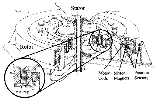
Magnetic bearings can be realised by using attractive or repulsive forces. A better mass vs. stiffness ratio can be achieved by using the attractive force mode [9]. Preference was given to the 2 DOF option where the wheel is actively controlled along two orthogonal radial directions where axial movements and all other degrees of rotor freedom are passively controlled by means of permanent magnets, except for the rotor spin. The two radial axes are independently controlled by their control loops. This design principle generally results in a flatter geometry, using less volume and being suitable for panel mounting. Moreover, the 2 DOF actively controlled bearing allows a high momentum-to-mass ratio of the wheel as parts of the bearing contribute to the momentum storage capacity. For position detection, four field displacement type inductive sensors are mounted with 90 degrees angular spacing around the flywheel, facing the outside rim surface.
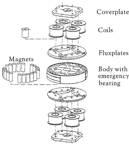
In the wheel design both permanent magnets and electromagnetic coils are used. Most of the DOF are passively controlled - this has the advantages of high reliability and low power consumption because the amount of electronics is reduced. The permanent magnets produce the main part of the magnetic flux in the magnetic circuit and the electromagnetic coils modulate this static bias flux, allowing the control of restoring forces on the wheel to keep it centered. This modulation is necessary to provide active control in the radial direction in the presence of imbalance or external forces. Another advantage is the linearised characteristic of force vs. current through the superposition of permanentmagnetic and electromagnetic fluxes [10]. Rare-earth permanent magnets were chosen because they offer a high energy density and have advantages in terms of mass and volume.

|

|
The inside diameter of the wheel consists of another ``C'-shaped magnetic return ring made of steel (1a) with a non-magnetic filling (1h) to act as a touchdown bearing in the radial direction. This emergency bearing will be used during launch and in case of a power failure. It prevents the return ring from touching the flux plates, thus maintaining a minimum air gap which is important to ensure lift-off of the bearing. The flux plates (3) and the return ring (1a) have tapered edges to increase the magnetic flux across the air gap and therefore improve the axial stiffness.

|
The magnetic finite element simulation allowed the rapid development of one engineering model of the momentum wheel within three months. Three flight versions with minor changes were built in nine further months. No ``trial-and-error` method with many breadboard models, long workshop and testing periods was necessary to validate the design. Properties like magnetic flux, force and stiffness parameters were obtained in a relatively short time from the simulations with much higher accuracy than with hand calculations. Most importantly, the function of the bearing design was validated in an early development state, where changes could be applied without great effort.
 |

|

|

|

|

|

|
Rare-earth magnets were used in this design as they were readily available at low cost and increase the motor performance substantially compared to ferrite magnets. The magnetic circuit of the motor assembly was optimised with the magnetic finite element simulation program MAFIA, thus optimising the amount of iron for the magnetic return ring without the danger of magnetic flux saturation. At the same time, the magnetic flux density could be increased, making the motor more efficient in terms of the torque-to-power ratio. Special care was taken to reduce the stray field outside the magnetic circuit which could otherwise induce eddy-current losses. The entire wheel design is kept as flat as possible and concentrates the motor mass closely at the rim so that it adds as much as possible to the moment of inertia.
The motor windings are embedded into two flat pieces of composite material which are separated by an angle of 180 degrees. This arrangement applies a symmetric torque and adds redundancy to the system. Three pairs of inductive field sensors located above the wheel provide the commutation signals. A number of holes is sequentially drilled into the upper part of the wheel structure, reducing the weight and generating field changes in the sensors. The sensor output signals are processed in the motor logic and connect the motor phases one at a time to the supply voltage. A motor controller keeps track of the wheel's total stored momentum thus simplifying the control of the spacecraft through the on-board computer software.
In practice, a maximum torque of 30 mNm was achieved. This allows the wheel to be accelerated from 0 to 3000 rpm within 8.5 minutes. As an option, the motor can be used as a generator to provide electric power for the magnetic bearing in case of a satellite power failure. The wheel is then decelerated safely to a rotation speed, where the mechanical safety bearing allows a safe touchdown between rotor and stator.
A motor controller keeps track of the wheel's total stored momentum and simplifies the control laws of the spacecraft's on-board computer software.
Table 2 summarises the main wheel and motor properties.
| Wheel | Diameter: | 280 mm |
| Rotating mass: | 3.66 kg | |
| Moment of inertia: | 0.049 kg m^2 | |
| Motor | Principle: | 3-phase brushless DC |
| Commutator sensors: | Inductive field type | |
| Maximum torque: | 30 mNm !hline |
| General characteristics | Momentum storage capacity: | 15 Nms @ 3000 rpm |
| Dimensions of housing: | 400 x 300 x 100 mm | |
| slew rate on Phase 3-D: | 6 degrees/min. | |
| Nominal speed: | 1000 rpm | |
| Maximal speed: | 3000 rpm | |
| Magnetic bearing | Type: | Radial active, axial passive |
| Diameter: | 100 mm | |
| Nominal radial gap | 1 mm | |
| Axial stiffness: | 80 N/mm, 95 N/mm simulated | |
| Radial stiffness: | 160 N/mm | |
| Tilting stiffness: | 0.4 Nm/rad | |
| Touchdown bearing | Mechanical gap: | 0.3 mm, two phenolic touchdown rings in axial and radial direction. |
| Lubrication: | Oil impregnation | |
| Launch acceleration: | Max. 5.5g | |
| Power consumption | Bearing: | Max. 5 Watts, 0 - 3000 rpm |
| Motor: | Max. 15 Watts @ 3000 rpm and full torque. | |
| Mass | Rotor: | 3.66 kg |
| Stator: | 2.5 kg | |
| Cables, casing: | ca. 2.5 kg | |
| Electronics: | 1 kg | |
| Total: | under 10 kg | |
| Sensors | Bearing: | 4 in radial direction, |
| 90 degrees angular spacing | ||
| Commutation: | 6 above the wheel | |
| Nutation: | 4 below the wheel | |
| All sensors are field displacement inductive sensors. |
A summary of the performance characteristics measured on the prototype model is given in Table 3. The three flight models are of the same design without significant differences in their properties. In future versions, the relatively moderate maximum wheel speed could increased, resulting in a gain in the angular momentum storage capacity. Angular momentum storage capacity is a function of mass (and its distribution), dimensions and speed. The maximum speed of the wheel to allow a safe touchdown is governed by the mechanical properties of the emergency bearing. With the motor in generator mode, the bearing can be supplied with power and the wheel slowed down smoothly until a lower rotation speed is reached. This overcomes the maximum speed limits set by the mechanical touchdown bearing.
Tests carried out on the wheel demonstrated that there are no critical rotation speeds in the full operating-speed range. No peaks in power consumption were noticed at particular speeds and no instabilities at any speed or wheel position in the Earth gravity environment were observed.
The power measurements were performed in the atmospheric environment. Future vacuum chamber tests are planned in the ESTEC labs to determine the eddy current losses, which are estimated to be a small fraction of the air-drag losses. In this way, the power consumption of the wheel in space can be determined. The wheel has a smooth shape (no spokes) and for in-air testing, all sensor holes were sealed with thin plastic foil. Moreover, the motor magnets are embedded into plastic to further reduce the air drag factor. With these precautions, a full operational checkout of the attitude control system of the spacecraft in air will be possible.