| Language | |
| English | |

Sun Sensor
- Fabrication Responsibility:
- Alan Bloom N1AL
Jason Kovatch N6BCI
Jake Sanderson KD6BCL
John Breckenridge WB6FRZ
Steve Whitelaw KD6FYK
Tim Bosma W6ISS
Steve Todd K2IYQ
Herb Sullivan K6QXB
Bruce Erickson KK6TG
Kurt Helstrom WA6TIP
Jim Hill K6UUW
Mike Drayton
Steve Hageman
Albert Kong
Karen Spencer
Denny Yamaoka
... and other students at the Santa Rosa Junior College electronics department at Santa Rosa, CA. - Size:
- 2x Special Package
- Average Power Dissipation:
- 0 Watts
Table of Contents
Rocket ScienceThe Phase 3D Satellite
Why a Sun Sensor?
What's Next?
Theory of operation of the sun sensor electronics board
Main Sensor
The PSD
AD538 Circuit Equations
Calibrating Pinhole Size
Circuit Details
Secondary Sensor
Component Selection
Specifications
Rocket Science
by Al Bloom, N1AL, 1997
We now have two bona fide rocket scientists in SCRA. John Breckenridge WB6FRZ and Alan Bloom N1AL have been involved in designing and building the Sun Sensor system on the upcoming Phase 3D (P3D) satellite to be launched by AMSAT. John designed and machined the sensor housing and Al did the electronics.
Back before Christmas, Herb Sullivan K6QXB, an electronics instructor at the Santa Rosa Junior College, attended the AMSAT annual meeting in Arizona where it was announced that P3D would need some way of determining the position of the sun. Herb must have never been in the Army, because he raised his hand and volunteered. At our first project meeting on Dec 9, we learned that the schedule called for "flight-ready" hardware to be fully assembled, tested, calibrated and shipped to AMSAT by Feb 1, 1997. Less than two months!
By the end of the project, 19 local radio amateurs and 4 non-hams had contributed in one way or another. A lot of work was accomplished in a very short time. Thanks to Hewlett Packard for PC board fabrication and providing many of the parts and tools for making both the electronics assembly, sensor housing and calibration fixtures. The Santa Rosa Junior College provided money for some expensive specialty components as well as testing facilities. Most of the people on the project were either HP employees or students or employees of the SRJC.
The Phase 3D Satellite
The last four issues of QST have contained articles on P3D, describing the orbit and the 10 different frequency bands you can use to talk through the bird. However, there were a couple topics they didn't cover.
Most satellites spin while they are in orbit. The gyroscopic effect helps to stabilize the bird's orientation. Spinning also helps with thermal regulation; otherwise the side facing the sun would get too hot and the side facing space (at around -270 degrees C) would get too cold.
However, P3D will be three-axis stabilized. That allows the antennas to point at the earth while the solar cells always point toward the sun. That also makes thermal management a big issue, especially on a satellite this big. By using heat pipes to channel the heat where needed and paying close attention to reflectivity and emissivity, AMSAT engineers can obtain a fairly constant temperature throughout the bird. Pointing the satellite in the proper direction is the job of three internal "reaction wheels" (giant gyroscopes) oriented on the X, Y and Z axes. The on-board computer in the Internal Housekeeping Unit (IHU) can spin the reaction wheels faster or slower to cause the satellite to precess to the proper orientation.
Why a Sun Sensor?
The Sun Sensor tells the IHU where the sun is, to help orient the spacecraft. This is not only for normal operation in the three- axis-stabilized mode, but also to orient the craft for rocket firings, so excellent accuracy is required.
The Sun Sensor uses a special-purpose photocell from Hamamatsu Photonics Co. called a "Position-Sensitive Detector" (PSD). Our sensor housing acts as a pinhole camera, so the sun forms a small spot of light on the surface of the PSD. The PSD has four electrical contacts, two that determine the spot's position along the X axis and two for the Y axis. Our electronics assembly converts the currents from the four contacts into a pair of voltages that represent the sun's position in the X and Y directions. These signals are sent to an analog-to-digital converter (ADC) in the IHU for processing.
What's Next?
Since we started this project, the launch date has been set back twice, due to problems at the European Space Agency. The latest date is September 8, on the second attempted launching of the brand-new Ariane 5 launch vehicle. (Don't ask what happened on the first attempt!) This is something of a test flight: P3D is the only active satellite, with the rest of the payload filled with ballast and test instrumentation. As compensation, AMSAT only had to pay a launch fee of $1,000,000 compared to the normal price of $40,000,000.
So why not become a rocket scientist yourself and gear up to work through the satellite? Most of the equipment can be purchased ready-made or you can go the homebrew route. With 10 bands to choose from, there's something for everyone. Borrow a friend's QSTs if you're not an ARRL member and read the articles to find out what you need. See you on 10 GHz!
Theory of operation of the sun sensor electronics board
The Sun Sensor system on the Phase 3D (P3D) amateur satellite detects the position of the sun when it is within the sensor's field of view, which is approximately +/- 45 degrees in the vertical Z direction and +/- 20 degrees in the horizontal Y direction. (Z and Y are per the spacecraft coordinate system.) The two analog output signals range from 0V (-20 or -45 degrees) to 2.5V (+20 or +45 degrees), with 1.25V representing the boresight of the sensor.
In addition, circuitry to support a secondary sun sensor system is included. In this mode 6 sensors, each with two photodiodes, are mounted in various locations on the satellite. By comparing the amplitudes of the signals from these 12 photodiodes, the sun's position can be roughly determined even when it is not within the main sensor's field of view. This circuitry was added at the last minute and the system has not been tested.
Main Sensor
The PSD
The Hamamatsu Position-Sensitive Detector is a 1-cm-square photocell coated with a clear resistive material. There are four electrodes along the four outer edges (X1, X2, Y1 and Y2) and a common connection on the back of the chip. In normal operation, the common connection is reverse-biased (positive voltage) and the 4 electrodes are maintained at the same potential, by such means as feeding them into the virtual ground summing nodes of four operational amplifiers.
When a small spot of light strikes the surface of the sensor, it generates a current at that point. The current flows through the resistive coating to the four electrodes, in proportion to the spot's closeness to each electrode. For example, if the spot is close to the X1 electrode, most of the current will flow to X1 and only a little to X2. It turns out that the relative current into the two electrodes is approximately proportional to the position of the spot:
X position = (X2-X1) / (X1+X2) = delta_X / sigma_Xand similar for the Y position. Dividing by sigma_X, the total "X" current, makes the result independent of the intensity of the light. So long as the spot position remains constant, doubling the intensity causes the currents at both X1 and X2 to double, so the position signal does not change.
AD538 Circuit Equations
The above equation requires an analog divider. The Analog Devices AD538 Real-Time Analog Computational Unit includes an analog divider and multiplier to perform the following computation:
Vo = Vy * (Vz/Vx)The Sun Sensor electronics board uses an operational amplifier to generate an (X2-X1)/2 signal which is applied to the Vz input to the AD538. ("X2-X1" is actually called "Z2-Z1" or "delta_Z" to correspond with spacecraft coordinates). Another op amp generates Z1+Z2 (sigma_Z) which goes to the Vx input, and a calibrated 2V reference is connected to Vy:
Z_out = 2V * (delta_Z/2) / sigma_Z = 1V * delta_Z / sigma_ZDelta_Z (and delta_Y) can be either positive or negative. Since the AD538 cannot handle negative numbers, a portion of sigma_Z is added to the AD538's Vz input, and then subtracted out again at the output. Since the internal feedback resistors in the AD538 are 25k, the exact equation for the Z signal is:
Z_out = 2V * (delta_Z/2 + sigma_Z * 25k/46.4k) / sigma_Z - 2V * 25k/46.4k = 1V * delta_Z / sigma_ZThe "46.4k" resistor at the output is actually a 42.2k resistor in series with a potentiometer to allow calibrating the offset voltage.
The Y input has a 20-degree field of view, versus 45 degrees for the Z input. For maximum resolution, the delta_Y signal is multiplied by 45/20 ~= 11k/5k before being applied to the AD538.
Calibrating Pinhole Size
The pinhole size on the sensor housing should be chosen to illuminate the PSD at the proper level. At maximum sun brightness, the sigma_Z and sigma_Y signals should never exceed +7V (+2V with respect to the +5V common reference). At minimum brightness, the sigma_* signals should never be less than +0.2V with respect to +5V. An LM339 quad comparator detects when either the X or Y signal is out of range. The SS_VALID output is 0V when the sensor is off, +1.25V when X and/or Y are out of range, and +2.5V when everything is working.
Calculations (see attached) indicate that the Hamamatsu sensor's sun sensitivity on earth, relative to space, should be 0.71 for a unit air mass (sun at 90 degree angle), 0.635 for a 1.5 air mass (sun at arcsin (1/1.5) = 42 degrees), and 0.539 for a 2.0 air mass (sun at arcsin (1/2) = 30 degrees). Santa Rosa CA is at a latitude of 38 deg N. On February 22 (solstice + 2 months), the sun should be approximately 40 degrees above the horizon at noon. 90 - (38 + 23.5 * cos (2*PI * 2/12)) = 40 degrees. To obtain a margin of 2 dB (1.58), the pinhole size should be selected so that the sigma_Z and sigma_Y signals are about 0.4 full scale (+0.8V with respect to +5V) at noon on a clear day in late February, with the sensor pointed directly at the sun.
Circuit Details
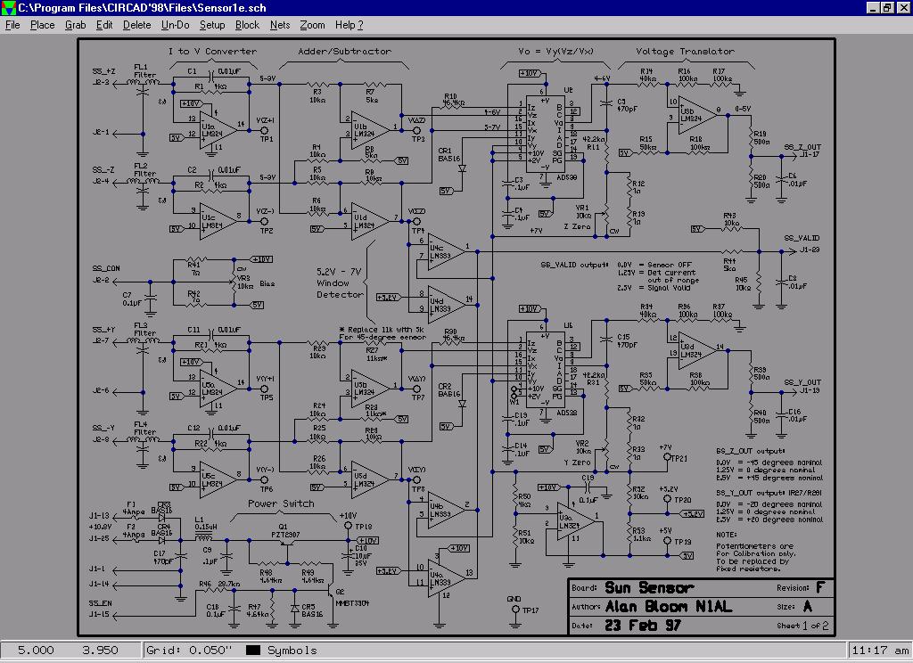 Page 1 of the schematic contains the circuitry for the main sun
sensor and the power supply switch. To allow for operation from
a single +10V supply, all of the main sensor circuitry is
referenced to +5V instead of to ground. +5V is generated by op
amp U3a, using the +2V reference of one of the AD538s.
Page 1 of the schematic contains the circuitry for the main sun
sensor and the power supply switch. To allow for operation from
a single +10V supply, all of the main sensor circuitry is
referenced to +5V instead of to ground. +5V is generated by op
amp U3a, using the +2V reference of one of the AD538s.
The AD538 is specified down to +/- 4.5V supplies. That means if the power supply falls below 9.5V, the AD538s are out of spec. On my breadboard, the reference voltage began to fall when the supply dropped to approximately 9.3V. The supply from the spacecraft is nominally +10.8V. After passing through the isolation diodes and switching transistor, it is about +9.9V. The sensor circuitry will work properly if the nominal +10.8V supply voltage is between approximately 10.4V and 20V.
Q1 and Q2 allow turning all circuitry on and off. Turn-on time is roughly 0.4 ms.
Potentiometers VR1 and VR2 adjust Z_out and Y_out so that 1.25V corresponds to zero degrees. VR3 adjusts the reverse bias on the sensor. For best reliability, all three potentiometers should be removed and replaced by fixed resistors once the proper values have been calibrated.
Each sensor electrode connects to an op amp configured as a current-to-voltage converter. Since the feedback resistors are 4k, +2V at sigma_* corresponds to 0.5 mA total at the two electrodes. If both sigma_Z and sigma_Y are at maximum, total sensor current is 1 mA. That is the maximum specified current from the Hamamatsu PSD. Operating at maximum signal level reduces susceptibility to noise and bias currents.
For both Z and Y, an additional output buffer op amp converts the 4-6V output of the AD538 to 0-5V, which is divided down to 0-2.5V by a resistive voltage divider. The output of LM324 op amps cannot go below about +0.6V when sinking current. The low-value load resistors (500 ohms) and high-value feedback resistors (150k total) allow the output to go to within 17 mV of ground, which is less than 2 LSBs of the spacecraft's 8-bit analog-to-digital converter.
Secondary Sensor
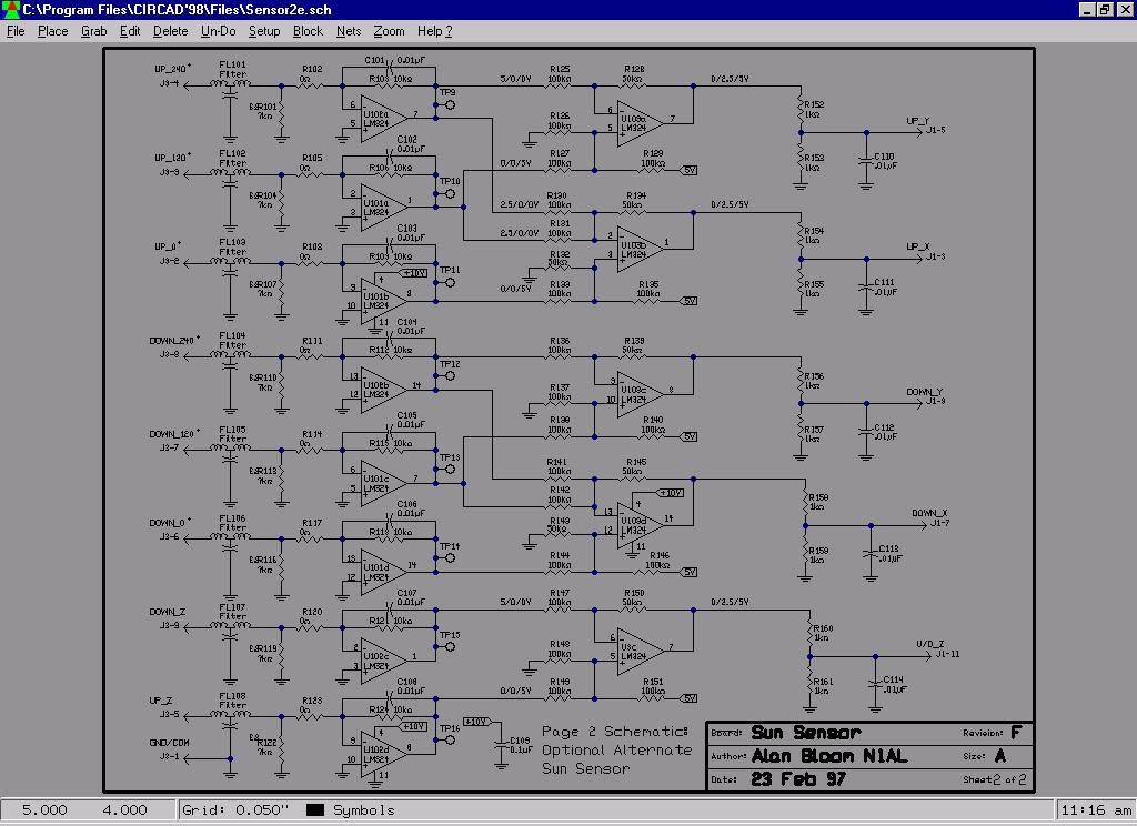 Page 2 of the schematic contains the circuitry for the secondary
sun sensor. 6 sensors are used, each with two photodiodes. It
is assumed that the "UP_0" sensor is mounted on the top of the
satellite with one photodiode pointed in the +X direction (same
as the solar panels) and one in the +Z direction. The "UP_120"
and "UP_240" sensors each have one photodiode pointing at 120
degrees or 240 degrees in the X/Y plane with respect to the 0
degree sensor, and the other photodiode pointing in the +Z
direction. Three similar sensors are mounted on the bottom of
the satellite with their "Z" photodiodes pointing in the -Z
direction.
Page 2 of the schematic contains the circuitry for the secondary
sun sensor. 6 sensors are used, each with two photodiodes. It
is assumed that the "UP_0" sensor is mounted on the top of the
satellite with one photodiode pointed in the +X direction (same
as the solar panels) and one in the +Z direction. The "UP_120"
and "UP_240" sensors each have one photodiode pointing at 120
degrees or 240 degrees in the X/Y plane with respect to the 0
degree sensor, and the other photodiode pointing in the +Z
direction. Three similar sensors are mounted on the bottom of
the satellite with their "Z" photodiodes pointing in the -Z
direction.
All photodiodes have their common (+) terminals tied to ground. The (-) terminals of the three "Z" photodiodes of the top sensors are connected in parallel to the "UP_Z" pin of J3, and the three bottom sensors to the "DOWN_Z" pin. The "U/D_Z_OUT" output is the difference between these two signals; positive voltage means the sun is toward the +Z direction.
The "UP_X_OUT" and "DOWN_X_OUT" signals are positive when the sun is toward the +X direction. They represent the difference between the 0-degree signal and 1/2 the sum of the 120- and 240- degree signals. Assuming the sensitivity of the photodiodes is proportional to the cosine of the direction, when the sun is in the -X direction, those two photodiodes will each be putting out 1/2 the maximum response: cos (+/- 60 deg) = 1/2
The "UP_Y_OUT" and "DOWN_Y_OUT" signals are positive when the sun is toward the +Y direction. They represent the difference between the 120-degree signal and the 240-degree signal. (120 degrees is assumed to be toward the +Y direction.)
Note that when the sun is within +/- 30 degrees (actually more than that) of the +X direction, the *_Y_OUT signals will be invalid. Similarly, when the sun is near the X/Y plane, the U/D_Z_OUT signal is invalid. When the sun is near the +Z or -Z direction, all the *X_OUT and *Y_OUT signals are invalid, unless the X/Y-plane photodiodes are angled slightly in the +/-Z direction.
The amount of current generated by the photodiodes is unknown. The feedback resistors on the input op amps (current to voltage converters) should be chosen to give maximum +2.5V signals at the outputs. Presumably R121 and R124 should be 1/3 the value of the others since they are driven by three diodes in parallel. If the current is high enough that op-amp output current is a concern, space for input series and shunt resistors is provided to bleed off some of the current.
Component Selection
LM124 operational amplifiers are known to be rad-hard. LM324s should be just as immune to radiation, since they use the same chips. The only difference between the two parts is that the LM124s are tested over the military temperature range. LM124s were not used since they are not available in surface-mount packages. The completed PC boards will be tested down to -60 degC to assure conformance with specifications.
The AD538 has only been tested to 10 krad. It is unknown if it would pass at 100 krad. Aluminum and tantalum shielding will be added to the board to protect the two AD538s from radiation.
Heat can be a concern in space applications since there is no convection cooling. Unlike through-hole components, surface- mount parts are cooled almost entirely via conduction of heat out the leads. 20-mil (0.5 mm) or wider traces were used throughout the board to improve heat conduction. Higher-dissipation components were connected to large copper foil areas to help radiate heat. Using a low supply voltage (10V) also reduces power dissipation.
Most of the resistors in the signal paths are 0.1% tolerance. In many places, 1% resistors would work fine. For example, any imbalance in the input summers/subtracters (U2b/d and U5b/d) can be eliminated by adjusting the Z_Zero and Y_Zero potentiometers. However, the reference resistors (R50/51) and the resistors around the output voltage translators (U3b/c/d, U103) should remain 0.1%.
The filters on the photodiode inputs each consist of a pair of ferrite beads in series and a 0.001 uF capacitor in shunt. It is unknown if these filters are needed or if they are adequate. These inputs go directly to op amp summing junctions which are sensitive to RF interference levels on the order of a few mV.
Specifications
| Operating temp: | -60 to +35 deg Celsius | |
| Storage temp: | -60 to +50 deg Celsius | |
| Radiation exposure: | 100 krad (With additional shielding for the AD538s, U2 and U6) | |
| Field of view: | +/- 45 degrees nominal, X-Z plane | |
| +/- 20 degrees nominal, X-Y plane (May be modified to +/- 45 degrees by changing R27 and R28 to 5k) | ||
| Inputs: | ||
| Supply voltage: | +10.4V to +20V | |
| Supply current: | 100 mA maximum at 10.8V | |
| SS_EN | +7V to +10V | Sensor enabled (ON) |
| 0V to +3V | Sensor disabled (OFF) | |
| Outputs: | ||
| SS_VALID: | 0V nominal | Sensor OFF |
| 1.25V nominal | Sensor output invalid | |
| 2.5V nominal | Sensor output valid | |
| SS_Z: | 0V nominal | -45 degrees |
| 1.25V +/-0.01V | 0 degrees | |
| 2.5V nominal | +45 degrees | |
| Monotonic over the range | ||
| SS_Y: | 0V nominal | -20 degrees |
| 1.25V +/-0.01V | 0 degrees | |
| 2.5V nominal | +20 degrees | |
| Monotonic over the range | ||
| UP_Y: | <1.25V nominal | -Y direction |
| >1.25V nominal | +Y direction | |
| DOWN_Y: | same as UP_Y | same as UP_Y |
| UP_X: | <1.25V nominal | -X direction |
| >1.25V nominal | +X direction | |
| DOWN_X: | same as UP_X | same as UP_X |
| U/D_Z: | <1.25V nominal | -Z direction |
| >1.25V nominal | +Z direction | |
All outputs are guaranteed not to go below ground or above 1/2 the supply voltage.
The voltage range of each output may be doubled (to 0 to +5V) by deleting the grounded output resistor.
Created: 1995-11-15
Updated: 2000-10-31
by Ralf Zimmermann, DL1FDT
This URL: http://www.RalfZimmermann.de/phase3d/sun_sensor.html